Fill Out Your Niceic Electrical Certificate Form
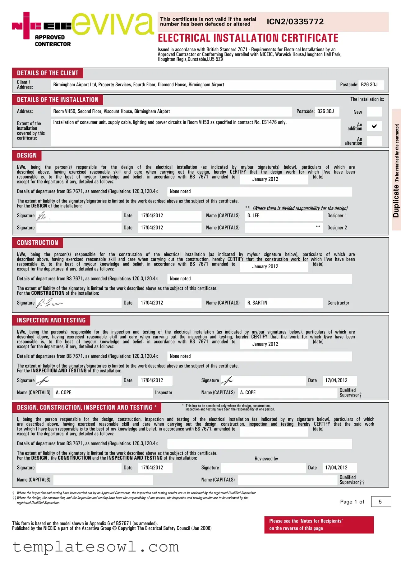
The NICEIC Electrical Certificate is a crucial document in the safety and compliance of electrical installations across the UK. Designed in accordance with British Standard 7671, this form acts as a testament to the work performed by an Approved Contractor or Conforming Body registered with the National Inspection Council for Electrical Installation Contracting (NICEIC). The certificate encompasses various aspects of the installation, including detailed information about the client, the specific installation site, and a comprehensive description of the work completed, such as the installation of consumer units, power circuits, and lighting systems. Essential signatures from the design, construction, and inspection parties affirm their commitment to industry standards and regulations, ensuring that the installation adheres to safety requirements. Additionally, the document includes areas for recording the characteristics of the supply system, earthing arrangements, and any recommendations for future inspections. Ultimately, the NICEIC Electrical Certificate serves as both a declaration of compliance and a vital reference for electrical safety in properties such as Birmingham Airport, where precision and adherence to standards are paramount.
Niceic Electrical Certificate Example
This certificate is not valid if the serial |
ICN2/0335772 |
|
number has been defaced or altered |
||
|
||
|
|
ELECTRICAL INSTALLATION CERTIFICATE
Issued in accordance with British Standard 7671 - Requirements for Electrical Installations by an
Approved Contractor or Conforming Body enrolled with NICEIC, Warwick House,Houghton Hall Park,
Houghton Regis,Dunstable,LU5 5ZX
DETAILS OF THE CLIENT
Client / |
Birmingham Airport Ltd, Property Services, Fourth Floor, Diamond House, Birmingham Airport |
Postcode: |
B26 3QJ |
|
Address: |
||||
|
|
|
DETAILS OF THE INSTALLATION |
|
|
|
|
|
|
|
|
|
|
|
|
|
|
|
|
|
|
|
|
|
|
|
|
|
|
|
|
|
|
|
|
|
|
|
|
|
|
|
The installation is: |
||||||||||||
Address: |
|
|
Room VH50, Second Floor, Viscount House, Birmingham Airport |
|
|
|
|
|
|
|
|
|
|
|
|
|
|
|
|
|
|
|
|
Postcode: |
B26 3QJ |
|
|
New |
|
|
||||||||||||||||||||||
|
|
|
|
|
|
|
|
|
|
|
|
|
|
|
|
|
|
|
|
|
|
|
|
|
|
|
|
|
|
|
|
|
|
|
|
|
|
|
||||||||||||||
Extent of the |
|
|
Installation of consumer unit, supply cable, lighting and power circuits in Room VH50 as specified in contract No. ES1476 only. |
|
|
|
|
|
|
|
|
|
|
|
|
|
||||||||||||||||||||||||||||||||||||
|
|
|
|
|
|
|
|
|
|
|
|
An |
á |
|
||||||||||||||||||||||||||||||||||||||
installation |
|
|
|
|
|
|
|
|
|
|
|
|
|
|
|
|
|
|
|
|
|
|
|
|
|
|
|
|
|
|
|
|
|
|
|
|
|
|
|
|
|
|
|
|
|
addition |
|
|||||
covered by this |
|
|
|
|
|
|
|
|
|
|
|
|
|
|
|
|
|
|
|
|
|
|
|
|
|
|
|
|
|
|
|
|
|
|
|
|
|
|
|
|
|
|
|
|
|
|
|
|
|
|
||
certificate: |
|
|
|
|
|
|
|
|
|
|
|
|
|
|
|
|
|
|
|
|
|
|
|
|
|
|
|
|
|
|
|
|
|
|
|
|
|
|
|
|
|
|
|
|
|
|
|
An |
|
|
||
|
|
|
|
|
|
|
|
|
|
|
|
|
|
|
|
|
|
|
|
|
|
|
|
|
|
|
|
|
|
|
|
|
|
|
|
|
|
|
|
|
|
|
|
|
|
|
alteration |
|
|
|||
|
|
|
|
|
|
|
|
|
|
|
|
|
|
|
|
|
|
|
|
|
|
|
|
|
|
|
|
|
|
|
|
|
|
|
|
|
|
|
|
|
|
|
|
|
|
|
|
|
|
|
|
|
|
|
|
|
|
|
|
|
|
|
|
|
|
|
|
|
|
|
|
|
|
|
|
|
|
|
|
|
|
|
|
|
|
|
|
|
|
|
|
|
|
|
|
|
|
|
|
|
|
|
|
|
|
DESIGN |
|
|
|
|
|
|
|
|
|
|
|
|
|
|
|
|
|
|
|
|
|
|
|
|
|
|
|
|
|
|
|
|
|
|
|
|
|
|
|
|
|
|
|
|
|
|
|
|
|
|
|
|
I/We, being the person(s) responsible |
for the design of the electrical |
installation |
|
(as |
indicated |
by |
|
my/our signature(s) |
|
below), |
particulars |
of |
which |
are |
|
|
||||||||||||||||||||||||||||||||||||
described above, having exercised reasonable skill and care when carrying |
out the design, hereby CERTIFY |
that |
the |
design |
work |
for which I/we have been |
|
|
||||||||||||||||||||||||||||||||||||||||||||
responsible is, |
to |
the best of my/our |
knowledge and |
belief, in |
accordance |
with BS |
7671 |
amended |
to |
|
|
|
|
January 2012 |
|
|
|
|
|
|
|
(date) |
|
|
|
|
|
|
|
|
||||||||||||||||||||||
except for the departures, if any, detailed as follows: |
|
|
|
|
|
|
|
|
|
|
|
|
|
|
|
|
|
|
|
|
|
|
|
|
|
|
|
|
|
|
|
|
|
|
|
|
|
|
||||||||||||||
|
|
|
|
|
|
|
|
|
|
|
|
|
|
|
|
|
|
|
|
|
|
|
|
|
|
|
|
|
|
|
|
|
|
|
|
|
|
|
|
|
|
|
|
|
|
|||||||
Details of departures from BS 7671, as amended (Regulations 120.3,120.4): |
|
None noted |
|
|
|
|
|
|
|
|
|
|
|
|
|
|
|
|
|
|
|
|
|
|
|
|
|
|
|
|
|
|
|
|||||||||||||||||||
The extent of liabilty of the signatory/signatories is limited to the work described above as the subject of this certificate. |
|
|
|
|
|
|
|
|
|
|
|
|
|
|
|
|
|
|
|
|
|
|
|
|
||||||||||||||||||||||||||||
For the DESIGN of the installation: |
|
|
|
|
|
|
|
|
|
|
|
|
|
|
|
|
|
|
|
|
|
|
** (Where there is divided responsibility for the design) |
|
|
|||||||||||||||||||||||||||
Signature |
|
|
|
|
|
|
|
|
|
|
Date |
|
17/04/2012 |
|
|
|
|
|
|
|
Name (CAPITALS) |
|
D. LEE |
|
|
|
|
|
|
|
|
|
|
|
Designer 1 |
|
|
|||||||||||||||
|
|
|
|
|
|
|
|
|
|
|
|
|
|
|
|
|
|
|
|
|
|
|
|
|
|
|
|
|
|
|
|
|
|
|
|
|
|
|
|
|
|
|
||||||||||
Signature |
|
|
|
|
|
|
|
|
|
|
Date |
|
17/04/2012 |
|
|
|
|
|
|
|
Name (CAPITALS) |
|
|
|
|
|
|
|
|
|
|
** |
Designer 2 |
|
|
|||||||||||||||||
|
|
|
|
|
|
|
|
|
|
|
|
|
|
|
|
|
|
|
|
|
|
|
|
|
|
|
|
|
|
|
|
|
|
|
|
|
|
|
|
|
|
|
|
|
|
|
|
|
|
|
|
|
|
|
|
|
|
|
|
|
|
|
|
|
|
|
|
|
|
|
|
|
|
|
|
|
|
|
|
|
|
|
|
|
|
|
|
|
|
|
|
|
|
|
|
|
|
|
|
|
|
||||
CONSTRUCTION |
|
|
|
|
|
|
|
|
|
|
|
|
|
|
|
|
|
|
|
|
|
|
|
|
|
|
|
|
|
|
|
|
|
|
|
|
|
|
|
|
|
|
|
|
|
|
|
|||||
I/We, being the person(s) responsible |
for the construction of the electrical |
installation |
(as |
indicated |
by |
my/our |
signature |
below), |
particulars |
of |
which |
are |
|
|
||||||||||||||||||||||||||||||||||||||
described above, having exercised reasonable skill and care when carrying out the construction, hereby CERTIFY that the construction work for which I/we have been |
|
|
||||||||||||||||||||||||||||||||||||||||||||||||||
responsible is, |
to |
the best of my/our |
knowledge and |
belief, in |
accordance |
with BS |
7671 |
amended |
to |
|
|
|
|
January 2012 |
|
|
|
|
|
|
|
(date) |
|
|
|
|
|
|
|
|
||||||||||||||||||||||
except for the departures, if any, detailed as follows: |
|
|
|
|
|
|
|
|
|
|
|
|
|
|
|
|
|
|
|
|
|
|
|
|
|
|
|
|
|
|
|
|
|
|
|
|
|
|
||||||||||||||
|
|
|
|
|
|
|
|
|
|
|
|
|
|
|
|
|
|
|
|
|
|
|
|
|
|
|
|
|
|
|
|
|
|
|
|
|
|
|
|
|||||||||||||
Details of departures from BS 7671, as amended (Regulations 120.3,120.4): |
|
None noted |
|
|
|
|
|
|
|
|
|
|
|
|
|
|
|
|
|
|
|
|
|
|
|
|
|
|
|
|
|
|
|
|||||||||||||||||||
The extent of liabilty of the signatory is limited to the work described above as the subject of this certificate. |
|
|
|
|
|
|
|
|
|
|
|
|
|
|
|
|
|
|
|
|
|
|
|
|
|
|
|
|||||||||||||||||||||||||
For the CONSTRUCTION of the installation: |
|
|
|
|
|
|
|
|
|
|
|
|
|
|
|
|
|
|
|
|
|
|
|
|
|
|
|
|
|
|
|
|
|
|
|
|
|
|
|
|
|
|||||||||||
Signature |
|
|
|
|
|
|
|
|
|
|
Date |
|
17/04/2012 |
|
|
|
|
|
|
|
Name (CAPITALS) |
|
R. SARTIN |
|
|
|
|
|
|
|
|
|
|
Constructor |
|
|
||||||||||||||||
|
|
|
|
|
|
|
|
|
|
|
|
|
|
|
|
|
|
|
|
|
|
|
|
|
|
|
|
|
|
|
|
|
|
|
|
|
|
|
|
|
|
|
|
|
|
|
|
|
|
|
|
|
|
|
|
|
|
|
|
|
|
|
|
|
|
|
|
|
|
|
|
|
|
|
|
|
|
|
|
|
|
|
|
|
|
|
|
|
|
|
|
|
|
|
|
|
|
|
|
||||||
INSPECTION AND TESTING |
|
|
|
|
|
|
|
|
|
|
|
|
|
|
|
|
|
|
|
|
|
|
|
|
|
|
|
|
|
|
|
|
|
|
|
|
|
|
|
|
|
|
|
|
|
|||||||
I/We, being the person(s) responsible for the inspection and testing of the electrical |
installation (as indicated by my/our |
signatures below), particulars of |
which |
are |
|
|
||||||||||||||||||||||||||||||||||||||||||||||
described above, having exercised reasonable skill and care when carrying out |
the inspection and testing, hereby CERTIFY that the work |
for which |
I/we |
have |
been |
|
|
|||||||||||||||||||||||||||||||||||||||||||||
responsible is, |
to |
the best of my/our |
knowledge and |
belief, in |
accordance |
with BS |
7671 |
amended |
to |
|
|
|
|
January 2012 |
|
|
|
|
|
|
|
(date) |
|
|
|
|
|
|
|
|
||||||||||||||||||||||
except for the departures, if any, detailed as follows: |
|
|
|
|
|
|
|
|
|
|
|
|
|
|
|
|
|
|
|
|
|
|
|
|
|
|
|
|
|
|
|
|
|
|
|
|
|
|
||||||||||||||
|
|
|
|
|
|
|
|
|
|
|
|
|
|
|
|
|
|
|
|
|
|
|
|
|
|
|
|
|
|
|
|
|
|
|
|
|
|
|
||||||||||||||
Details of departures from BS 7671, as amended (Regulations 120.3,120.4): |
|
None noted |
|
|
|
|
|
|
|
|
|
|
|
|
|
|
|
|
|
|
|
|
|
|
|
|
|
|
|
|
|
|
|
|||||||||||||||||||
The extent of liabilty of the signatory/signatories is limited to the work described above as the subject of this certificate. |
|
|
|
|
|
|
|
|
|
|
|
|
|
|
|
|
|
|
|
|
|
|
|
|
||||||||||||||||||||||||||||
For the INSPECTION AND TESTING of the installation: |
|
|
|
|
|
|
|
|
|
|
|
|
|
|
|
|
|
|
|
|
|
|
|
|
|
|
|
|
|
|
|
|
|
|
|
|
|
|
|
|
|
|||||||||||
Signature |
|
|
|
|
|
|
|
|
|
|
Date |
|
17/04/2012 |
|
|
|
|
|
|
|
Signature |
|
|
|
|
|
|
|
|
|
|
|
|
|
|
|
Date |
17/04/2012 |
|
|
|
|
||||||||||
|
|
|
|
|
|
|
|
|
|
|
|
|
|
|
|
|
|
|
|
|
|
|
|
|
|
|
|
|
|
|
|
|
|
|
|
|
|
|
|
|
|
|
|
|
|
|
|
|
|
|
||
|
|
|
|
|
|
|
|
|
|
|
|
|
|
|
|
|
|
|
|
|
|
|
|
|
|
|
|
|
|
|
|
|
|
|
|
|
|
|
|
|
|
|
|
|
|
|
Qualified |
|
|
|||
Name (CAPITALS) |
A. COPE |
|
|
|
|
|
|
Inspector |
|
|
|
|
Name (CAPITALS) |
|
A. COPE |
|
|
|
|
|
|
|
|
|
|
|
|
|
|
|
||||||||||||||||||||||
|
|
|
|
|
|
|
|
|
|
|
|
|
|
|
|
|
|
|
|
|
|
|
|
SupervisorÚ |
|
|
||||||||||||||||||||||||||
|
|
|
|
|
|
|
|
|
|
|
|
|
|
|
|
|
|
|
|
|
|
|
|
|
|
|
|
|
|
|
|
|
|
|
|
|
|
|
|
|
|
|
|
|
|
|
|
|
|
|
|
|
|
|
|
|
|
|
|
|
|
|
|
|
|
|
|
|
|
|
|
|
|
|
|
|
|
|
|
|
|
|
|
|
|
|
|
|
|
|
|
||||||||||||||
DESIGN, CONSTRUCTION, INSPECTION AND TESTING * |
|
|
|
|
* |
This box to be completed only where the design, construction, |
|
|
|
|
|
|
|
|
|
|
|
|
|
|
|
|
||||||||||||||||||||||||||||||
|
|
|
|
|
inspection and testing have been the responsibility of one person. |
|
|
|
|
|
|
|
|
|
|
|
|
|
|
|
|
|||||||||||||||||||||||||||||||
I, being the person |
responsible for the |
design, construction, |
inspection |
and |
testing |
of |
the |
electrical |
installation (as |
indicated |
by my |
signature below), particulars of which |
||||||||||||||||||||||||||||||||||||||||
are described |
above, |
having exercised |
reasonable skill |
and |
care |
when |
carrying |
out |
the design, |
|
construction, |
inspection |
and |
testing, |
hereby CERTIFY that the said work |
|||||||||||||||||||||||||||||||||||||
for which I have been responsible is to the best of my knowledge and belief, in accordance with BS 7671, amended to |
|
|
|
|
|
|
|
|
|
|
|
|
|
|
(date) |
|
|
|
|
|
|
|
|
|||||||||||||||||||||||||||||
except for the departures, if any, detailed as follows: |
|
|
|
|
|
|
|
|
|
|
|
|
|
|
|
|
|
|
|
|
|
|
|
|
|
|
|
|
|
|
|
|
|
|
|
|
|
|
|
|
|
|||||||||||
Details of departures from BS 7671, as amended (Regulations 120.3,120.4): |
|
|
|
|
|
|
|
|
|
|
|
|
|
|
|
|
|
|
|
|
|
|
|
|
|
|
|
|
|
|
|
|
|
|
|
|
||||||||||||||||
The extent of liabilty of the signatory is limited to the work described above as the subject of this certificate. |
|
|
|
|
|
|
|
|
|
|
|
|
|
|
|
|
|
|
|
|
|
|
|
|
|
|
|
|||||||||||||||||||||||||
For the DESIGN , the CONSTRUCTION and the INSPECTION AND TESTING of the installation: |
|
|
|
|
|
|
|
|
|
|
Reviewed by |
|
|
|
|
|
|
|
|
|
|
|
|
|
|
|
|
|||||||||||||||||||||||||
Signature |
|
|
|
|
|
|
|
|
|
|
Date |
|
17/04/2012 |
|
|
|
|
|
|
|
Signature |
|
|
|
|
|
|
|
|
|
|
|
|
|
|
|
Date |
17/04/2012 |
|
|
|
|
||||||||||
Name (CAPITALS) |
|
|
|
|
|
|
|
|
|
|
|
|
|
|
|
|
|
|
|
Name (CAPITALS) |
|
|
|
|
|
|
|
|
|
|
|
|
|
|
|
|
|
|
Qualified |
|
|
|||||||||||
|
|
|
|
|
|
|
|
|
|
|
|
|
|
|
|
|
|
|
|
|
|
|
|
|
|
|
|
|
|
|
|
|
|
|
|
|
|
|
||||||||||||||
|
|
|
|
|
|
|
|
|
|
|
|
|
|
|
|
|
|
|
|
|
|
|
|
|
|
|
|
|
|
|
|
|
|
|
|
|
SupervisorÚÚ |
|
|
|||||||||||||
|
|
|
|
|
|
|
|
|
|
|
|
|
|
|
|
|
|
|
|
|
|
|
|
|
|
|
|
|
|
|
|
|
|
|
|
|
|
|
|
|
|
|
|
|
|
|
|
|
|
|
|
|
ÚWhere the inspection and testing have been carried out by an Approved Contractor, the inspection and testing results are to be reviewed by the registered Qualified Supervisor. ÚÚ Where the design, the construction, and the inspection and testing have been the responsibilty of one person, the inspection and testing results are to be reviewed by the
registered Qualified Supervisor. |
Page 1 of |
5 |
Duplicate (To be retained by the contractor)
This form is based on the model shown in Appendix 6 of BS7671 (as amended).
Published by the NICEIC a part of the Ascertiva Group © Copyright The Electrical Safety Council (Jan 2008)
Please see the 'Notes for Recipients' on the reverse of this page
This certificate is not valid if the serial |
ICN2/0335772 |
|
number has been defaced or altered |
||
|
||
|
|
PARTICULARS OF THE ORGANISATION(S) RESPONSIBLE FOR THE ELECTRICAL INSTALLATION
DESIGN (1) |
Organisation |
Ú Eviva Services Ltd |
|
|
|
|
|
|
|
|
|
|
|
|
|
|
|
Rapide Building |
|
NICEIC Enrolment No |
502741000 |
|
|
Address: |
|
|
|||||
|
|
Ramp Road |
|
|
(where appropriate) |
|
|
|
|
|
|
|
|
||
|
|
Birmingham Airport |
|
Branch number: |
|
|
|
|
|
Birmingham |
|
|
|
|
|
|
|
|
Postcode: B26 3QJ |
(if applicable) |
|
|
|
|
|
West Midlands |
|
|
|||
|
|
|
|
|
|||
|
|
|
|
|
|
|
|
DESIGN (2) |
Organisation |
Ú |
|
|
|
|
|
|
|
|
|
|
|
|
|
|
|
|
|
|
NICEIC Enrolment No |
|
|
Address: |
|
|
|
|
|
||
|
|
|
(where appropriate) |
|
|
||
|
|
|
|
|
|
|
|
|
|
|
|
|
Branch number: |
|
|
|
|
|
|
|
|
|
|
|
|
|
|
Postcode: |
(if applicable) |
|
|
|
|
|
|
|
|
|
|
|
|
|
|
|
|
|
|
Ú |
Organisation |
Eviva Services Ltd |
|
|
|
|
|
CONSTRUCTION |
|
|
|
|
|
|
|
|
|
Rapide Building |
|
NICEIC Enrolment No |
502741000 |
|
|
Address: |
|
|
|||||
|
|
Ramp Road |
|
|
(Essential Infomation) |
|
|
|
|
|
|
|
|
||
|
|
Birmingham Airport |
|
Branch number: |
|
|
|
|
|
Birmingham |
|
|
|
|
|
|
|
|
Postcode: B26 3QJ |
(if applicable) |
|
|
|
|
|
West Midlands |
|
|
|||
|
|
|
|
|
|||
|
|
|
|
|
|
|
|
INSPECTION |
Organisation |
Ú Eviva Services Ltd |
|
|
|
|
|
AND TESTING |
|
|
|
|
|
|
|
|
|
|
|
|
|
|
|
|
|
Rapide Building |
|
NICEIC Enrolment No |
502741000 |
|
|
Address: |
|
|
|||||
|
|
Ramp Road |
|
|
(where appropriate) |
|
|
|
|
|
|
|
|
||
|
|
Birmingham Airport |
|
Branch number: |
|
|
|
|
|
Birmingham |
|
|
|
|
|
|
|
|
Postcode: B26 3QJ |
(if applicable) |
|
|
|
|
|
West Midlands |
|
|
|||
|
|
|
|
|
|||
SUPPLY CHARACTERISTICS AND EARTHING ARRANGEMENTS |
Tick boxes and enter details, as appropriate |
|
|
Duplicate (To be retained by the contractor)
Ý System Type(s) |
Ý Number and Type of Live Conductors
Nature of Supply Parameters
Ý Characteristics of Primary Supply |
N/A |
|
|
|
N/A |
|
|
|
TT |
N/A |
|
|
IT |
N/A |
|
|
Other
a.c. |
á |
|
|
d.c. |
|
|
|
2 pole |
|||
N/A |
N/A |
||||
(3 wire) |
|||||
|
|
|
|
|
|
N/A |
|
|
|
3 pole |
|
|
|
|
|
|
|
N/A |
á |
other |
|||
(4 wire) |
|||||
|
|
|
|
|
|
|
|
|
|
|
|
N/A
N/A
N/A
Nominal Uþ Voltage(s):
Nominal frequency, fþ
Prospective fault current, IÙÄÅ
External earth fault loop impendance, Ñ ÄÅ
Number of supplies
400
50
>20
0.01
1
V
Hz
kA
É
UÒþ 230 V
Notes:
(1)by enquiry
(2)by enquiry or by measurement
(3)where more than one supply, record the higher or highest values
(4)by measurement
Overcurrent Protective Device(s) |
BS(EN) |
BS EN |
|
||
|
|
|
|
|
|
|
|
|
|
Type |
MCCB |
|
|
|
|
|
|
|
|
|
|
|
|
|
Rated current630 |
|
A |
||
|
|
|
||
|
|
|
||
50 |
|
kA |
||
capacity |
|
|||
|
|
|
|
|
PARTICULARS OF INSTALLATION AT THE ORIGIN |
|
Tick boxes and enter details, as appropriate |
|
|
|
|
|
|
|
|
|
|
|
|
|
|
|
|
|||||||||||||||||||
Ý Means of Earthing |
|
|
|
|
|
Type: |
|
Details of Installation Earth Electrode (where applicable) |
|
|
|
|
|
|
|
|
|
|
|
|
|
|
|
|
|
|
|||||||||||
|
|
|
|
|
|
|
|
|
|
|
|
|
|
|
|
|
|
|
|
|
|
|
|
||||||||||||||
Distributor's |
|
á |
|
|
|
|
N/A |
|
|
|
Location: |
N/A |
|
|
|
|
|
|
|
|
|
|
|
|
|
|
|
|
|
|
|
|
|
||||
|
|
(eg rod(s),tape etc) |
|
|
|
|
|
|
|
|
|
|
|
|
|
|
|
|
|
|
|
|
|
|
|
|
|||||||||||
facility: |
|
|
|
|
|
|
|
|
|
|
|
|
|
|
|
|
|
|
|
|
|
|
|
|
|
|
|||||||||||
Installation |
|
N/A |
|
|
|
Electrode |
N/A |
(É) |
|
Method of |
N/A |
|
|
|
|
|
|
|
|
|
|
|
|
|
|
|
|
|
|
|
|
|
|||||
|
|
resistance, RÕ: |
|
measurement: |
|
|
|
|
|
|
|
|
|
|
|
|
|
|
|
|
|
|
|
|
|
||||||||||||
earth electrode: |
|
|
|
|
|
|
|
|
|
|
|
|
|
|
|
|
|
|
|
|
|
|
|
|
|
|
|
|
|||||||||
|
|
|
|
|
|
|
|
|
|
|
|
|
|
|
|
|
|
|
|
|
|
|
|
|
|
|
|
|
|
|
|||||||
Ý Main Switch or |
|
|
|
|
|
Maximum |
|
|
|
|
|
Amps |
|
|
|
|
|
|
|
Protection measure |
|
|
|
|
|
|
|
|
|
||||||||
|
|
|
|
|
630 |
|
|
|
|
|
|
|
|
|
ADS |
|
|
|
|
|
|
|
|
||||||||||||||
* (applicable only where an RCD is suitable and is used as a main |
|
Demand (Load) |
|
|
|
|
|
|
|
|
|
against electric shock: |
|
|
|
|
|
|
|
|
|||||||||||||||||
|
|
|
|
|
|
|
|
|
|
|
|
|
|
|
|
|
|
|
|||||||||||||||||||
Type: |
BS EN |
|
Voltage |
415 |
|
|
|
|
|
|
|
|
|
|
|
|
|
|
|
|
|
|
|
|
|
|
|
|
|
|
|
|
|||||
|
V |
|
|
|
|
|
|
|
|
Protective Bonding Conductors |
|
|
|
|
|
|
|
|
|
|
|||||||||||||||||
BS(EN) |
|
rating |
|
|
|
|
|
|
|
|
|
|
|
|
|
|
|
|
|
|
|||||||||||||||||
|
|
|
|
|
|
|
|
Rated |
|
|
|
Earthing conductor |
|
|
Main protective bonding conductors |
|
|
Bonding of |
|
|
|
|
|
||||||||||||||
No of |
3 |
|
|
|
|
|
|
630 |
A |
Conductor |
Copper |
|
|
Conductor |
Copper |
|
|
|
|
|
Water |
á |
Gas |
á |
|
|
|
|
|
|
|||||||
Poles |
|
|
|
|
current,IÐ |
|
material |
|
|
material |
|
|
|
|
|
service |
Service |
|
|
|
|
|
|
||||||||||||||
Supply |
|
|
|
|
|
RCD operating |
|
|
Conductor |
|
|
|
|
|
Conductor |
|
|
|
|
|
|
|
Oil |
|
Structural |
á |
|
|
|
|
|
|
|||||
conductors |
Copper |
|
|
N/A |
mA |
120 |
|
|
mmâ |
|
70 |
|
|
mmâ |
|
N/A |
|
|
|
|
|
|
|||||||||||||||
|
|
current, IÜ * |
|
|
|
|
|
|
|
|
|
|
service |
steel |
|
|
|
|
|
|
|||||||||||||||||
material |
|
|
|
|
|
|
|
|
|
|
|
csa |
|
|
|
|
|
|
csa |
|
|
|
|
|
|
|
|
|
|
|
|
|
|
|
|
|
|
Supply |
|
|
|
|
mmâ |
RCD operating |
|
|
Continuity |
á |
|
(á) |
|
|
Continuity] |
á |
|
(á) |
|
|
|
Lightning |
á |
Other incoming |
|
N/A |
|
|
|
|
|
|
|||||
conductors |
240 |
|
|
time (atIÜ )* |
N/A |
ms |
|
|
|
|
|
|
|
protection |
service(s) |
|
|
|
|
|
|
|
|||||||||||||||
csa |
|
|
|
|
check |
|
|
|
|
|
check |
|
|
|
|
|
|
|
|
|
|
|
|
|
|||||||||||||
|
|
|
|
|
|
|
|
|
|
|
|
|
|
|
|
|
|
|
|
|
|
|
|
|
|
|
|
|
|
|
|
|
|
|
|||
|
|
|
|
|
|
|
|
|
|
|
|
|
|
|
|
|
|
|
|
|
|
|
|
|
|
|
|
|
|
||||||||
COMMENTS ON EXISTING INSTALLATION |
|
|
|
|
|
|
|
|
|
|
|
|
|
|
|
|
|
|
|
|
|
|
|
|
|
|
|
|
|||||||||
|
|
|
|
|
|
|
|
|
|
|
|
|
|
|
|
|
|
|
|
|
|
|
Note: Enter 'NONE' or, where appropriate, the page number(s) |
|
|
|
|
|
|||||||||
|
|
|
|
|
In the case of an alteration or additions see Section 633 |
|
|
|
|
|
|
|
|
|
|
|
|
|
|
||||||||||||||||||
|
|
|
|
|
|
|
|
|
|
|
|
|
|
of addional page(s) of comments on the existing installation. |
|
|
|
|
|
||||||||||||||||||
|
|
|
|
|
|
|
|
|
|
|
|
|
|
|
|
|
|
|
|
|
|
|
|
|
|
|
|
|
|
|
|
|
|
|
|
|
|
|
|
|
|
|
|
|
|
|
|
|
|
|
|
|
|
|
|
|
|
|
|
|
|
|
|
|
|
|
|
|
|||||||
NEXT INSPECTION |
|
ò Enter interval in terms of years, months or weeks, as appropriate |
|
|
|
|
|
|
|
|
|
|
|
|
|
|
|
|
|
|
|
|
|
|
|
|
|
||||||||||
|
|
|
|
|
|
|
|
|
|
|
|
|
|
|
|
|
|
|
|
|
ò |
Five Years |
|
|
|
|
|
|
|
|
|
|
|||||
I/We the designer(s), RECOMMEND that this installation is further inspected and tested after an interval of not more than |
|
|
|
|
|
|
|
|
|
|
|||||||||||||||||||||||||||
|
|
|
|
|
|
|
|
|
|
|
|
|
|
|
|
|
|
|
|
|
|
|
|
|
|
|
|
|
|
|
|
|
|
|
|
|
|
Ú Where the Approved Contractor responsible for the construction of the electrical installation has also been responsible for the designand the inspection and testing |
|
|
|
|
|
|
|
|
|
|
|
|
|
|
|
|
|||||||||||||||||||||
of that installation, the 'Particulars of the Organisation responsible for the Electrical Installation' may be recorded only in the section entitled 'CONSTRUCTION' |
|
|
|
|
|
|
|
Page 2 of |
|
5 |
|
|
|
||||||||||||||||||||||||
Ý Where a number of sources are available to supply the installation, and where the data given for the primary source may differ from other sources, |
|
|
|
|
|
|
|
|
|
|
|
|
|
||||||||||||||||||||||||
a separate sheet must be provided which identifies the relevant information relating to each additional source. |
|
|
|
|
|
|
|
|
|
|
|
|
|
|
|
|
|
|
|
|
|
|
|
|
|
||||||||||||
This form is based on the model shown in Appendix 6 of BS7671 (as amended).
Published by the NICEIC a part of the Ascertiva Group © Copyright The Electrical Safety Council (Jan 2008)
Please see the 'Notes for Recipients' on the reverse of this page
This certificate is not valid if the serial |
ICN2/0335772 |
|
number has been defaced or altered |
||
|
||
|
|
|
SCHEDULE OF ITEMS INSPECTED |
|
|
Ú See note below |
||||||
|
PROTECTIVE MEASURES AGAINST ELECTRIC SHOCK |
|
||||||||
|
|
|
|
|
|
|
|
|
|
|
|
|
Basic and fault protection |
|
|
|
|
|
|
||
|
Extra low voltage |
|
|
|
|
|
||||
|
N/A |
SELV |
N/A |
|
PELV |
|||||
|
Double or reinforced insulation |
|
|
|
|
|||||
|
|
|
Double or Reinforced Insulation |
|
||||||
|
N/A |
|
||||||||
|
|
|
|
|
|
|
|
|
||
|
|
Basic Protection |
|
|
|
|
|
|
||
|
|
|
|
|
|
|
|
|||
|
á |
Insulation of live parts |
á |
|
|
Barriers or enclosures |
||||
|
|
|
|
|
||||||
|
N/A |
Obstacles ** |
N/A |
|
Placing out of reach ** |
|||||
|
|
|
|
|
|
|
|
|
|
|
Fault protection
Automatic disconnection of supply
áPresence of earthing conductor
áPresence of circuit protective conductors
áPresence of main protective bonding conductors
|
Presence of earthing arrangements for combined |
|
N/A |
||
protective and functional purposes |
||
|
||
|
Presence of adequate arrangements for alternative |
|
N/A |
||
source(s), where applicable |
||
|
N/A |
FELV |
|
|
áChoice and setting of protective and monitoring devices (for fault protection and/or overcurrent protection)
N/A |
Absence of protective conductors |
|||
|
|
Presence of |
||
N/A |
||||
Electrical separation |
||||
|
|
For one item of current using equipment |
||
N/A |
||||
|
|
For more than one item of current using equipment** |
||
N/A |
||||
|
|
|
|
|
|
Additional protection |
|
|
|
|
|
|
|
|
|
Presence of residual current device(s) |
|||
N/A |
||||
|
|
|
|
|
áPresence of supplementry bonding conductors
**for use in controlled supervised/conditions only
Prevention of mutual detrimental influence
áProximity of
áSegregation of Band I and Band II circuits or Band II insulation used
áSegregation of safety Circuits
Identification
áPresence of diagrams, instructions, circuit charts and similar information
áPresence of danger notices and other warning notices
áLabelling of protective devices, switches and terminals
áidentification of conductors
Cables and Conductors
áSelection of conductors for current carrying capacity and voltage drop
áErection methods
áRouting of cables in prescribed zones
áCables incorporating earthed armour or sheath or run in an earthed wiring system, or otherwise protected against nails, screws and the like
Additional protection by 30mA RCD for cables concealed in walls
N/A (where required,in premises not under the supervision of skilled or instructed persons)
áConnection of conductors
áPresence of fire barriers, suitable seals and protection against thermal effects
General
áPresence and correct location of appropriate devices for isolation and switching
áAdequacy of access to switchgear and other equipment
N/A |
Particular protective measures for special installations and locations |
|
|
áConnection of
áCorrect connection of accessories and equipment
N/A |
Presence of undervoltage protective devices |
|
|
áSelection of equipment and protective measures appropriate to external influences
áSelection of appropriate functional switching devices
Duplicate (To be retained by the contractor)
SCHEDULE OF ITEMS TESTED |
Ú See note below |
|
|
áExternal earth fault loop impendance,Ñ
N/A |
Installation earth electrode resistance, RÕ |
|
|
áContinuity of protective conductors
áContinuity of ring final circuit conductors
áInsulation resistance between live conductors
áInsulation resistance between live conductors and Earth
N/A |
Protection by seperation of circuits |
|
|
N/A
N/A
á
á
á
N/A
á
á
Basic protection by barrier or enclosure provided during erection
Insulation of
Polarity
Earth fault loop impendance,Ö
Verification of phase sequence
Operation of resudual current devices
Functional testing of assemblies
Verification of voltage drop
SCHEDULE OF ADDITIONAL RECORDS* (See attached schedule) |
Page No(s) |
|
Note: Additional page(s) must be identified by the Electrical Installation Certificate serial number and page number(s).
ÚAll boxes must be completed. 'á' indicates that an inspection or a test was carried out and that the result was satisfactory. 'N/A' indicates that an
inspection or a test was not applicable to the particular installation |
Page 3 of |
5 |
*Where the electrical works to which this certificate relates includes the installation of a fire alarm system and/or an emergency lighting system (or a part of such system), this electrical safety certificate should be accompanied by the particular certificate(s) for the system(s).
This form is based on the model shown in Appendix 6 of BS7671 (as amended).
Published by the NICEIC a part of the Ascertiva Group © Copyright The Electrical Safety Council (Jan 2008)
This certificate is not valid if the serial |
ICN2/0335772 |
|
number has been defaced or altered |
||
|
||
|
|
SCHEDULE OF CIRCUIT DETAILS
FOR THE INSTALLATION
CIRCUIT DETAILS
TO BE COMPLETED IN EVERY CASE |
|
TO BE COMPLETED ONLY IF THE DISTRIBUTION BOARD IS NOT CONNECTED DIRECTLY TO THE ORIGIN OF THE INSTALLATION* |
|||||||||||
|
|
|
|
|
|
|
|
|
|
|
|
|
|
Location of |
|
|
|
|
|
|
|
|
|
|
|
|
|
VH50, Second Floor, Viscount |
|
Supply to distribution |
|
|
|
|
No of |
|
Nominal |
|
|
||
|
Landlords Distribution Panel T2 circuit 5L3 |
|
1 |
230 |
V |
||||||||
distribution board: |
House |
|
|
||||||||||
|
board is from: |
|
phases: |
voltage: |
|||||||||
|
|
|
|
|
|
|
|
|
Associated |
N/A |
|
|
|
|
|
|
Overcurrent protective device for the distribution circuit: |
|
|
RCD (if any): BS(EN) |
|
|
|
||||
|
|
|
|
|
|
|
|
|
|||||
Distribution |
DB T2/5L3 |
|
Type: |
BS 3871 MCB Type 2 |
Rating: |
45 |
A |
RCD No |
N/A |
IÜ |
N/A |
mA |
|
board designation: |
|
BS(EN) |
of poles: |
||||||||||
|
|
|
|
|
|
|
|
|
|
|
|
|
|
|
Circuit designation |
|
|
|
|
|
Circuit |
Max. disconnection time permitted |
|
Overcurrent protective devices |
|
RCD |
7671 |
||
|
|
|
|
|
conductors: csa |
|
|
||||||||
Circuit number and phase |
|
Type of wiring |
(see code) |
|
Number of points served |
Live |
cpc |
|
BS (EN) |
|
|
|
|
BS |
|
|
|
|
|
by BS 7671 |
|
|
Operating current, IÜ |
Maximum Ö permitted by |
|||||||
|
Reference method |
|
|
|
Type No |
Rating |
|||||||||
|
|
|
|
|
|
(mmâ) |
(mmâ) |
(s) |
|
|
|
(A) |
(kA) |
(mA) |
(É) |
1 /L1 |
Ring Main |
B/E |
|
B |
10 |
4.0 |
2.5 |
0.2 |
|
60898 MCB |
C |
32 |
10 |
N/A |
0.72 |
|
|
|
|||||||||||||
2 /L1 |
Lighting |
B |
|
B |
6 |
2.5 |
2.5 |
0.2 |
|
60898 MCB |
C |
16 |
10 |
N/A |
1.44 |
|
|
|
|||||||||||||
3 /L1 |
|
|
|
|
|
|
|
|
|
|
|
|
|
|
|
4 /L1
Duplicate (To be retained by the contractor)
Þ See Table 4A2 of Appendix 4 of BS 7671
|
|
|
|
|
CODES |
FOR TYPE OF |
WIRING |
|
A |
B |
C |
D |
E |
F |
G |
H |
O (Other - please state) |
|
|
|
|
|
|
|
|
|
PVC/PVC |
PVC cable |
PVC cables |
PVC cables |
PVC cables |
PVC/SWA |
XLPE/SWA |
Mineral- |
|
cables |
in metallic |
in |
in metallic |
in |
cables |
cables |
insulated |
|
|
conduit |
conduit |
trunking |
trunking |
|
|
cables |
|
|
|
|
|
|
|
|
|
|
* In such cases, details of the distribution
Page 4 of
5
This form is based on the model shown in Appendix 6 of BS7671 (as amended).
Published by the NICEIC a part of the Ascertiva Group © Copyright The Electrical Safety Council (Jan 2008)
See next page for Schedule of Test Results
TO BE COMPLETED ONLY IF THE DISTRIBUTION BOARD IS NOT CONNECTED
DIRECTLY TO THE ORIGIN OF THE INSTALLATION
Characteristics at this distribution board
|
|
Yes |
|
|
|
|
|
Confirmation of supply polarity |
|
|
|
|
|
|
|||||||||||||||
|
|
|
|
|
|
|
|
|
|
|
|
|
|
|
|
|
|
|
|
|
|
|
|
|
|
|
|
|
|
* See note below |
|
|
|
|
|
|
|
|
|
|
|
|
|
|
|
|
|
|
|
|
|
||||||||
Ö |
*0.32 |
|
|
|
|
É |
|
|
|
Operating times |
At IÜ |
|
N/A |
|
|
ms |
|||||||||||||
|
|
|
|
|
|
|
|
|
|
|
|
|
|
|
|
of associated |
|
|
|
|
|
|
|
|
|||||
|
|
|
|
|
|
|
|
|
|
|
|
|
|
|
|
|
|
|
|
|
|
|
|
||||||
IÙ |
*0.66 |
|
|
|
|
|
kA |
|
|
|
|
RCD (if any) |
At 5IÜ |
|
N/A |
|
|
ms |
|||||||||||
|
|
|
|
|
|
|
|
|
|
|
|
|
|
|
|
|
|
|
|
|
|
|
|
|
|
|
|
|
|
|
|
|
|
|
|
|
|
|
|
|
|
|
|
|
|
|
|
|
|
|
|
|
|
|
|
|
|
|
|
|
|
|
|
|
|
|
|
|
|
|
|
|
|
|
|
|
Circuit impedances |
|
|
|
|
|
|
|
|
|
|||
|
numberCircuit |
phaseand |
|
|
|
|
|
|
|
|
|
|
|
|
|
(É) |
|
|
|
|
|
|
|
|
|
|
|
||
|
|
|
|
|
|
Ring final circuits only |
|
|
|
All |
circuits |
|
|
|
|||||||||||||||
|
|
|
|
|
|
|
|
|
(measured end to end) |
|
|
(At least |
one column |
||||||||||||||||
|
|
|
|
|
|
|
|
|
|
|
|
|
|
|
|
|
|
|
|
|
|
|
to be |
completed) |
|||||
|
|
|
|
|
|
|
|
|
|
|
|
|
|
|
|
|
|
|
|
|
|
|
|
|
|
|
|
|
|
|
|
|
|
|
|
|
rã |
|
|
|
|
|
rÐ |
|
|
rå |
|
|
|
|
|
|
|
|
|
||||
|
|
|
|
|
|
|
|
|
|
|
|
|
|
|
|
|
|
|
|
|
|
||||||||
|
|
|
|
|
|
(Line) |
|
|
|
(Neutral) |
|
|
(cpc) |
|
Rã + Rå |
|
Rå |
||||||||||||
|
|
|
|
|
|
|
|
|
|
|
|
|
|
|
|
|
|
|
|
|
|
|
|
|
|
|
|
|
|
|
1 /L1 |
|
|
0.15 |
|
|
|
|
015 |
|
|
|
0.25 |
|
|
|
0.10 |
|
|
|
N/A |
|
|||||||
|
|
|
|
|
|
|
|
|
|
|
|
|
|
|
|
|
|
|
|
||||||||||
|
2 /L1 |
|
|
N/A |
|
|
|
|
N/A |
|
|
|
N/A |
|
|
|
0.21 |
|
|
|
N/A |
|
|||||||
|
|
|
|
|
|
|
|
|
|
|
|
|
|
|
|
|
|
|
|
|
|
|
|
|
|
|
|||
|
3 /L1 |
|
|
|
|
|
|
|
|
|
|
|
|
|
|
|
|
|
|
|
|
|
|
|
|
|
|
||
|
|
|
|
|
|
|
|
|
|
|
|
|
|
|
|
|
|
|
|
|
|
|
|
|
|
|
|||
|
4 /L1 |
|
|
|
|
|
|
|
|
|
|
|
|
|
|
|
|
|
|
|
|
|
|
|
|
|
|
||
|
|
|
|
|
|
|
|
|
|
|
|
|
|
|
|
|
|
|
|
|
|
|
|
|
|
|
|
|
|
|
This certificate is not valid if the serial |
ICN2/0335772 |
|
number has been defaced or altered |
|
|
|
|
|
|
|
|
SCHEDULE OF TEST RESULTS |
|
|
FOR THE INSTALLATION |
|
|
TEST RESULTS |
|
|
|
|
|
Test instruments (serial numbers) used: |
|
Earth fault loop |
|
7014230 |
|
|
|
|
|
|
|
RCD |
|
|
|
|
|
|
|
|
|
|
|
|
||||||
impedance |
|
|
|
|
|
|
|
|
|
|
|
|
|
|
|
|
|
|
|
|
||||||||
|
|
|
|
|
|
|
|
|
|
|
|
|
|
|
|
|
|
|
|
|
|
|
|
|
|
|||
Insulation |
|
|
|
|
|
|
|
|
|
|
|
Other |
|
|
|
|
|
|
|
|
|
|
|
|
||||
|
6027902 |
|
|
|
|
|
|
|
|
|
|
|
|
|
|
|
|
|
|
|
||||||||
resistance |
|
|
|
|
|
|
|
|
|
|
|
|
|
|
|
|
|
|
|
|
||||||||
|
|
|
|
|
|
|
|
|
|
|
|
|
|
|
|
|
|
|
|
|
|
|
|
|
|
|||
Continuity |
|
|
|
|
|
|
|
|
|
|
Other |
|
|
|
|
|
|
|
|
|
|
|
|
|||||
|
6027902 |
|
|
|
|
|
|
|
|
|
|
|
|
|
|
|
|
|
|
|
||||||||
|
|
|
|
|
|
|
|
|
|
|
|
|
|
|
|
|
|
|
|
|
|
|
|
|
|
|
|
|
|
|
|
|
|
|
|
|
|
|
|
|
|
|
|
|
|
|
|
|
|
|
|
|
|
|
|
|
|
|
|
|
|
|
|
|
|
|
|
|
|
|
|
|
|
|
|
|
|
|
|
|
|
|
|
|
|
|
|
|
|
|
Insulation |
resistance |
|
|
|
Polarity |
|
|
Maximum |
|
|
|
RCD |
operating |
|||||||||||
|
|
|
|
|
|
|
|
|
|
|
|
|
|
|
|
|
measured earth |
|
|
|
times |
|||||||
|
|
|
|
|
|
|
|
|
|
|
|
|
|
|
|
|
|
fault loop |
at IÜ |
|
|
at 5IÜ |
||||||
Line/Line Ú |
Line/Neutral Ú |
Line/Earth Ú |
Neutral/Earth Ú |
|
|
|
|
impedance, Ö |
|
|
||||||||||||||||||
|
|
|
|
|
|
|
|
|
|
|
|
|
|
|
|
|
|
* See note below |
|
|
|
|
|
(if applicable) |
||||
(MÉ) |
|
(MÉ) |
(MÉ) |
(MÉ) |
(á) |
|
(É) |
|
|
(ms) |
|
|
|
(ms) |
||||||||||||||
|
|
|
|
|
|
|
|
|
|
|
|
|
|
|
|
|
|
|
|
|
|
|
|
|
|
|
|
|
|
N/A |
|
|
200 |
|
|
200 |
|
|
200 |
|
|
á |
|
|
|
0.42 |
|
|
N/A |
|
|
|
|
N/A |
|
||
|
|
|
|
|
|
|
|
|
|
|
|
|
|
|
|
|
|
|
|
|
|
|
|
|
|
|
|
|
|
N/A |
|
|
200 |
|
|
200 |
|
|
200 |
|
|
á |
|
|
|
0.53 |
|
|
N/A |
|
|
|
|
N/A |
|
||
|
|
|
|
|
|
|
|
|
|
|
|
|
|
|
|
|
|
|
|
|
|
|
|
|
|
|
|
|
|
|
|
|
|
|
|
|
|
|
|
|
|
|
|
|
|
|
|
|
|
|
|
|
|
|
|
|
|
|
|
|
|
|
|
|
|
|
|
|
|
|
|
|
|
|
|
|
|
|
|
|
|
|
|
|
|
|
Duplicate (To be retained by the contractor)
*Note: Where the installation can be supplied by more than one source, such as primary source (eg public supply) and a secondary source (eg standby generator), the higher or highest values must be recorded.
TESTED BY
Signature: |
|
Position: |
Technical Engineer |
|
|
|
|||
|
|
Date of |
|
|
|
|
|
|
|
Name: |
A. COPE |
16/04/2012 |
|
|
(CAPITALS) |
testing: |
|
||
|
|
|
||
|
|
|
|
|
This form is based on the model shown in Appendix 6 of BS7671 (as amended).
Published by the NICEIC a part of the Ascertiva Group © Copyright The Electrical Safety Council (Jan 2008)
Page 5 of
See previous page for Schedule of Circuit Details
5
Form Characteristics
| Fact Name | Description |
|---|---|
| Issuing Body | This electrical certificate is issued by NICEIC, a recognized authority in the UK for electrical safety. |
| Valid Serial Number | The certificate must display an intact serial number, ICN2/0335772. Any alteration renders it invalid. |
| Regulatory Compliance | The form is compliant with British Standard 7671, which outlines the safety requirements for electrical installations. |
| Details of the Installation | Information about the client's installation, including the address, will appear on the certificate. In this case, it is for Birmingham Airport’s Room VH50. |
| Signatories' Liability | The liability of the signatories is confined to the work described in the certificate. This emphasizes the importance of the specified tasks being carried out diligently. |
| Inspection Timeliness | It is recommended that the installation be inspected and tested again within five years to ensure ongoing compliance and safety. |
Guidelines on Utilizing Niceic Electrical Certificate
Filling out the Niceic Electrical Certificate form is an important task that ensures compliance with electrical installation standards. Careful attention should be paid to each section to guarantee accuracy and completeness. Here are the steps to guide you through the process.
- Start with the Certificate Number: Enter the certificate number in the designated field, ensuring the serial number remains unaltered.
- Client Details: Fill out the client’s name, address, and postcode. For example, use: Birmingham Airport Ltd, Diamond House, Birmingham Airport, B26 3QJ.
- Installation Details: Provide a precise address of the installation along with particulars like the extent of the project and the specific location within the premises—Room VH50, Second Floor, Viscount House, Birmingham Airport, B26 3QJ.
- Design Section: Identify the individual(s) responsible for the design. Include their signatures and dates. If there are multiple designers, list them all.
- Construction Section: Similar to the design section, indicate those accountable for construction. Again, provide their signatures and dates.
- Inspection and Testing Section: Record the names, signatures, and dates of those who performed the inspection and testing of the installation.
- Schedule of Items Inspected: Tick the relevant boxes that apply based on the inspection outcomes and provide additional comments if needed.
- Schedule of Test Results: Document test results. It is crucial to include serial numbers of the test instruments used and ensure all fields are filled accurately.
- Circuit Details: Complete the schedule of circuit details for the installation, mention associated distribution boards, and reference relevant codes.
- Final Review: Ensure all sections are completely filled and signatures are present in the necessary areas. Check compliance with the standards mentioned for validity.
After completing the form, keep in mind that any errors could invalidate the certificate. Take your time to review it thoroughly to ensure that everything is filled out correctly before submission. This careful preparation helps to maintain safety and compliance in electrical installations.
What You Should Know About This Form
What is the NICEIC Electrical Certificate form?
The NICEIC Electrical Certificate form is an important document issued for electrical installations. It confirms that the work carried out meets the necessary safety standards, particularly the British Standard 7671. Only approved contractors or organizations enrolled with NICEIC can issue this certificate, indicating that the work has been completed in compliance with the regulations.
Who issues the NICEIC Electrical Certificate?
The NICEIC Electrical Certificate is issued by approved contractors or organizations that are part of the National Inspection Council for Electrical Installation Contracting (NICEIC). These entities are qualified to ensure that electrical installations comply with safety and performance standards.
What information is included in the certificate?
The certificate includes crucial details such as the client’s information, the installation site, description of the work completed, and the signatures of the responsible parties (designers, constructors, inspectors). It verifies that the installation meets the current regulations and mentions any departures from those regulations if applicable.
Is the NICEIC Electrical Certificate valid forever?
No, the NICEIC Electrical Certificate is not valid indefinitely. It typically outlines a recommended inspection interval, often suggesting that the installation undergo further inspection and testing within five years. Regular checks help ensure ongoing safety and compliance with current standards.
What should I do if the serial number is defaced or altered?
If the certificate's serial number is defaced or altered, the document is considered invalid. It is crucial to keep the certificate in a safe condition. In case of damage, contact the issuing contractor for guidance on obtaining a replacement certificate.
Can I make changes to the installation after receiving the certificate?
Yes, changes can be made after receiving the NICEIC Electrical Certificate. However, any significant alterations or additions may require a new certificate. It’s advisable to consult with a qualified electrician to determine if the changes affect compliance with the safety standards.
Who is responsible for the accuracy of the information on the certificate?
The responsibility lies with the individuals who sign the certificate. Designers, constructors, and inspectors each confirm that they have exercised reasonable skill and care in their respective roles. The extent of their liability is limited to the specific work described in the certificate.
What happens during the inspection and testing mentioned in the certificate?
During the inspection and testing, specific checks are done to ensure that the electrical installation is safe and compliant. This includes examining protective measures against electric shock, verifying the continuity of conductors, and ensuring insulation resistance is adequate. These steps are crucial for identifying any potential safety hazards.
How can I find the NICEIC approved contractor for my project?
You can find NICEIC approved contractors by visiting the NICEIC website. They provide a search function to help you locate qualified contractors in your area. This is essential to ensure that your electrical work is done safely and is compliant with regulations.
Common mistakes
When filling out the Niceic Electrical Certificate form, people often overlook certain critical details. One common mistake is failing to verify the serial number. The certificate becomes invalid if the serial number, ICN2/0335772, is altered or defaced. Ensure this number is correct and placed prominently at the top of the form to avoid complications later.
Another frequent error is neglecting to provide full contact information for all responsible parties. This includes not only the client and the location of the installation but also the names and roles of those who designed, constructed, and inspected the installation. Incomplete information can lead to misunderstandings regarding accountability and responsibilities.
In addition, many fail to detail any departures from standards as outlined in BS 7671. If there are no departures, this should be explicitly stated as "None noted." Omitting this information can create ambiguity about compliance with safety standards. Each section must clearly reflect whether any deviations have occurred during the installation process.
Lastly, signatures and dates are sometimes incorrect or missing entirely. Each signatory must provide their signature and the appropriate date in the designated sections. Incorrect dates or failing to have all required signatures can invalidate the certificate. Therefore, double-check that all areas requiring signatures are completed properly and that the information is current.
Documents used along the form
The NICEIC Electrical Certificate is an essential document in the electrical installation process, ensuring safety and compliance with standards. Along with this certificate, there are several other important forms and documents that help in documenting and assessing the performance of electrical systems. The following list outlines these supplementary documents.
- Electrical Installation Condition Report (EICR): This report assesses the safety and condition of existing electrical installations. It identifies any issues that may require attention or correction to ensure continued safety.
- Periodic Inspection Report: This report details the observations and testing results from periodic inspections of electrical installations. It outlines the performance of the system and highlights any areas that need improvements.
- Minor Works Certificate: This document is used for minor electrical work that does not require a full certificate. It verifies that the work meets necessary standards and is safe for use.
- Declaration of Conformity: This declaration confirms that the installation complies with all relevant safety standards and regulations. It provides evidence of adherence to legal requirements.
- Test Results Record: This document captures all the test results conducted during installation and inspection of electrical systems. It serves as a comprehensive record of performance and safety checks.
- Installation Design Specification: This specification outlines the design parameters and considerations for a particular electrical installation. It provides guidance on how the installation should be configured for optimal performance and safety.
- Manufacturer's Test Certificate: This certificate is issued by the equipment manufacturer and verifies that the equipment has passed specific safety and performance tests before installation.
Each of these documents plays a critical role in ensuring the safety, compliance, and performance of electrical installations. Together, they provide a comprehensive view of the installation process from design to inspection, contributing to the overall integrity of electrical work.
Similar forms
- Electrical Inspection Report: Similar to the NICEIC Electrical Certificate, this report details the findings of an electrical safety inspection. It includes the inspector’s observations on compliance with safety standards, and confirms whether the installation is safe to use.
- Electrical Testing Certificate: This document certifies that various tests have been carried out on an electrical installation. Like the NICEIC certificate, it indicates compliance with relevant safety standards and includes test results and observations.
- Periodic Inspection Report (PIR): Issued after a visual inspection and testing of an electrical installation, the PIR identifies any deteriorated or unsafe wiring. It parallels the NICEIC Electrical Certificate by covering safety compliance regularly.
- Installation Certificate: This certificate attests that the electrical installation has been completed and is safe to use. It focuses on confirming compliance with regulations, similar to how the NICEIC certificate verifies electrical work.
- Minor Electrical Works Certificate: This document is used for smaller electrical changes and installations. Like the NICEIC certificate, it certifies the work done complies with safety standards but for minor installations specifically.
- Compliance Certificate for Energy-Using Products: This certificate ensures that electrical products meet specific environmental and safety standards. It has similarities with the NICEIC certificate in terms of confirming compliance but focuses more on product-level safety guidelines.
Dos and Don'ts
When filling out the NICEIC Electrical Certificate form, follow these essential guidelines to ensure accuracy and compliance.
- Thoroughly Read Instructions: Familiarize yourself with the entire form and requirements outlined in British Standard 7671.
- Verify All Information: Double-check details such as client information, installation specifics, and signatures to avoid discrepancies.
- Use Clear Capital Letters: Fill in names and important information in capital letters to enhance legibility and ensure precise identification.
- Submit in Time: Complete and submit the form promptly to ensure the certification process is not delayed.
- Avoid Altering Serial Numbers: Do not deface or change any serial numbers on the form, as this invalidates the certificate.
- Do Not Leave Blanks: Ensure every necessary section is completed; empty fields can lead to processing issues.
- Skip Hasty Answering: Take time to provide accurate information—rushed entries can lead to errors.
- Avoid Common Abbreviations: Use full terminologies instead of shortcuts which can cause confusion or misinterpretation.
Misconceptions
There are several misconceptions about the NICEIC Electrical Certificate form. Here’s a list of nine common ones:
- The certificate is valid regardless of the condition of the serial number. The certificate becomes invalid if the serial number has been defaced or altered.
- All electrical work must be certified using the NICEIC Electrical Certificate. Only the installations that comply with British Standard 7671 and are performed by approved contractors require this specific certification.
- Once issued, the certificate does not need to be reviewed. The certificate should be reviewed periodically, especially after significant electrical work.
- There is no limit to the liability of signatories on the certificate. The liability of the individuals signing the certificate is limited to the specific work described within it.
- This certificate guarantees the installation is completely safe. While it indicates compliance with regulations, it does not assure that all future issues will be resolved or that conditions won’t change.
- The certificate can be issued even if there are departures from standards. Departures must be documented and are only acceptable if they are clearly noted in the required section.
- All inspection and testing results are automatically satisfactory. Each result must be signed off and noted properly; ‘N/A’ means that a test was not applicable, not that it was completed successfully.
- Inspectors and testers are interchangeable. Different individuals perform design, construction, inspection, and testing, and each has distinct responsibilities.
- The certificate does not require specific details of individual circuits. Each circuit used in the installation must be documented within the certificate to ensure accountability and clarity.
Understanding these misconceptions can help ensure that electrical installations are safe, compliant, and professionally managed.
Key takeaways
Filling out and using the NICEIC Electrical Certificate form effectively is crucial for ensuring compliance with electrical safety standards. Here are key takeaways to guide you:
- Validity of the Certificate: Ensure that the serial number on the certificate is intact and unaltered for it to be considered valid.
- Client Information: Complete the client section with accurate details to ensure proper documentation. This includes the client's name, address, and postcode.
- Installation Details: Clearly specify the location and nature of the electrical installation. Any alterations or additions to the initial installation should be documented appropriately.
- Design Certification: Those responsible for the design must certify that their work adheres to the relevant standards. Record any exceptions or deviations explicitly.
- Liability Limitation: The extent of liability for those signing the document is limited to the specific work outlined in the certificate. This provision is critical for clarifying responsibility.
- Inspection and Testing: The individuals responsible for inspection and testing must also sign to confirm that all work meets the required standards and report any deficiencies.
- Next Inspection Date: Indicate the recommended interval for the next inspection clearly. Keeping records of prior inspections aids in maintaining compliance and safety.
- Record Additional Notes: Use additional pages if necessary, particularly for detailed observations or testing results related to the installation.
By keeping these takeaways in mind, the process of completing and utilizing the NICEIC Electrical Certificate form becomes more straightforward and ensures adherence to safety protocols.
Browse Other Templates
How Long Can I Suspend My Fehb Plan - If you opt not to enroll, this must be clearly indicated on the form.
Articles of Organization Pa - The inclusion of additional provisions is at the discretion of the organizers, subject to certain regulations.
Fort Valley College - Printing or signing the application signifies your agreement to the university’s regulations and policies.