Fill Out Your Manual J Form
The Manual J form is a critical tool utilized in the HVAC industry for determining heating and cooling loads in residential spaces. Specifically designed for homes built in Utah’s dry climate, it requires detailed calculations based on individual room loads, which are essential for accurate duct sizing. This form encompasses a range of information including project location, design conditions, infiltration methods, and heating/cooling calculations. Proper documentation of specifics such as outside and inside temperature values, design temperature differentials, and airflow rates is required. Furthermore, the form necessitates justification for any adjustments made to recommended values from the ACCA Manual J standards. The Manual J form also includes sections for entering specifications of heating and cooling equipment used, providing vital details such as the furnace's Annual Fuel Utilization Efficiency (AFUE) and the air conditioning unit’s Seasonal Energy Efficiency Ratio (SEER). Through systematic load calculations, the Manual J form enables stakeholders to gain a comprehensive understanding of energy requirements, ensuring the designed HVAC system functions efficiently throughout its lifespan.
Manual J Example

Building Services & Civil Enforcement slcpermits.com
451 South State Street, Room 215 |
PO Box 145490 |
Salt Lake City, Utah 84111 |
Salt Lake City, Utah |
Office only |
Updated 12/2012 |
BLD #  Received by
Date  Valuation
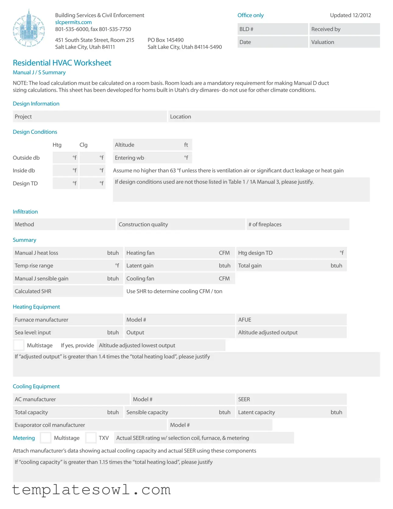
Residential HVAC Worksheet
Manual J / S Summary
NOTE: The load calculation must be calculated on a room basis. Room loads are a mandatory requirement for making Manual D duct sizing calculations. This sheet has been developed for homs built in Utah’s dry dimares- do not use for other climate conditions.
Design Information |
|
|
|
|
|
|
|
|
|
|
|
|
|
|
|
|
|
|
|
|
|
|
|
|
|
|||||
|
|
|
|
|
|
|
|
|
|
|
|
|
|
|
|
|
|
|
|
|
|
|
|
|
|
|
|
|
|
|
|
Project |
|
|
|
|
|
|
|
|
|
|
|
|
|
|
Location |
|
|
|
|
|
|
|
|
|
|
|
|||
|
|
|
|
|
|
|
|
|
|
|
|
|
|
|
|
|
|
|
|
|
|
|
|
|
|
|
|
|
|
|
Design Conditions |
|
|
|
|
|
|
|
|
|
|
|
|
|
|
|
|
|
|
|
|
|
|
|
|
|
|||||
|
|
|
|
|
|
|
|
|
|
|
|
|
|
|
|
|
|
|
|
|
|
|
|
|
|
|
|
|
||
|
|
Htg |
Clg |
|
|
Altitude |
|
|
ft |
|
|
|
|
|
|
|
|
|
|
|
|
|
||||||||
|
|
|
|
|
|
|
|
|
|
|
|
|
|
|
|
|
|
|
|
|
|
|
|
|
|
|
|
|
|
|
|
|
|
|
|
|
|
|
|
|
|
|
|
|
|
|
|
|
|
|
|
|
|
|
|
|
|
|
|||
Outside db |
|
|
°f |
|
|
°f |
|
Entering wb |
|
|
°f |
|
|
|
|
|
|
|
|
|
|
|
|
|
||||||
|
|
|
|
|
|
|
|
|
|
|
|
|
|
|
|
|
|
|
|
|
|
|
|
|
|
|
|
|
||
|
|
|
|
|
|
|
|
|
|
|
|
|
|
|
|
|
||||||||||||||
Inside db |
|
|
°f |
|
|
°f |
|
Assume no higher than 63 °f unless there is ventilation air or significant duct leakage or heat gain |
||||||||||||||||||||||
|
|
|
|
|
|
|
|
|
|
|
|
|
|
|
|
|
|
|
|
|
|
|
|
|
|
|
|
|||
|
|
|
|
|
|
|
|
|
|
|
|
|
|
|
|
|
|
|
|
|
|
|
|
|
|
|
|
|
|
|
Design TD |
|
|
°f |
|
|
°f |
|
If design conditions used are not those listed in Table 1 / 1A Manual 3, please justify. |
|
|
|
|
||||||||||||||||||
|
|
|
|
|
|
|
|
|
|
|
|
|
|
|
|
|
|
|
|
|
|
|
|
|
|
|
||||
|
|
|
|
|
|
|
|
|
|
|
|
|
|
|
|
|
|
|
|
|
|
|
|
|
|
|
|
|
|
|
Infiltration |
|
|
|
|
|
|
|
|
|
|
|
|
|
|
|
|
|
|
|
|
|
|
|
|
|
|
|
|
|
|
|
|
|
|
|
|
|
|
|
|
|
|
|
|
|
|
|
|
|
|
|
|
|
|
|
|
|
|
|
||
|
|
|
|
|
|
|
|
|
|
|
|
|
|
|
|
|
|
|
|
|
|
|
|
|
|
|
|
|
|
|
|
Method |
|
|
|
|
|
|
|
|
Construction quality |
|
|
|
|
|
|
|
|
# of fireplaces |
|
|
|
|
|
||||||
|
|
|
|
|
|
|
|
|
|
|
|
|
|
|
|
|
|
|
|
|
|
|
|
|
|
|
|
|
|
|
Summary |
|
|
|
|
|
|
|
|
|
|
|
|
|
|
|
|
|
|
|
|
|
|
|
|
|
|
|
|
|
|
|
|
|
|
|
|
|
|
|
|
|
|
|
|
|
|
|
|
|
|
|
|
|
|
|
|
|
||||
|
Manual J heat loss |
|
|
|
|
btuh |
|
Heating fan |
|
|
|
|
CFM |
|
Htg design TD |
|
°f |
|
|
|
||||||||||
|
|
|
|
|
|
|
|
|
|
|
|
|
|
|
|
|
|
|
|
|
|
|
|
|
|
|
|
|||
|
|
|
|
|
|
|
|
|
|
|
|
|
|
|
|
|
|
|
|
|
|
|
|
|
|
|
|
|||
|
Temp rise range |
|
|
|
|
to |
|
|
°f |
|
Latent gain |
|
|
|
|
btuh |
|
Total gain |
|
|
btuh |
|
|
|
||||||
|
|
|
|
|
|
|
|
|
|
|
|
|
|
|
|
|
|
|
|
|
|
|
|
|
|
|
|
|
||
|
|
|
|
|
|
|
|
|
|
|
|
|
|
|
|
|
|
|
|
|
|
|
|
|
|
|
|
|
||
|
Manual J sensible gain |
|
|
|
btuh |
|
Cooling fan |
|
|
|
|
CFM |
|
|
|
|
|
|
|
|
|
|
||||||||
|
|
|
|
|
|
|
|
|
|
|
|
|
|
|
|
|
|
|
|
|
|
|
|
|
|
|
|
|
|
|
|
|
|
|
|
|
|
|
|
|
|
|
Use SHR to determine cooling CFM / ton |
|
|
|
|
|
|
|
|
|
|
||||||||
|
Calculated SHR |
|
|
|
|
|
|
|
|
|
|
|
|
|
|
|
|
|
|
|
|
|||||||||
|
|
|
|
|
|
|
|
|
|
|
|
|
|
|
|
|
|
|
|
|
|
|
|
|
|
|
|
|
|
|
Heating Equipment |
|
|
|
|
|
|
|
|
|
|
|
|
|
|
|
|
|
|
|
|
|
|
|
|
|
|||||
|
|
|
|
|
|
|
|
|
|
|
|
|
|
|
|
|
|
|
|
|
|
|
|
|
|
|
|
|||
|
Furnace manufacturer |
|
|
|
|
|
|
|
Model # |
|
|
|
|
|
|
|
AFUE |
|
|
|
|
|
|
|||||||
|
|
|
|
|
|
|
|
|
|
|
|
|
|
|
|
|
|
|
|
|
|
|
|
|
|
|
|
|||
|
|
|
|
|
|
|
|
|
|
|
|
|
|
|
|
|
|
|
|
|
|
|
|
|
|
|
|
|||
|
Sea level: input |
|
|
|
|
|
|
btuh |
|
Output |
|
|
|
|
|
|
|
Altitude adjusted output |
|
|
|
|
||||||||
|
|
|
|
|
|
|
|
|
|
|
|
|
|
|
|
|
|
|
|
|
|
|
|
|
|
|
|
|||
|
Multistage |
|
If yes, provide |
|
|
|
|
|
|
|
|
|
|
|
|
|
|
|
|
|
|
|
||||||||
|
|
Altitude adjusted lowest output |
|
|
|
|
|
|
|
|
|
|
|
|
|
|||||||||||||||
|
|
|
|
|
|
|
|
|
|
|
|
|
|
|
|
|
|
|
|
|
|
|
|
|
|
|||||
|
|
|
|
|
|
|
|
|
|
|
|
|
|
|
|
|
|
|
|
|
|
|
|
|
||||||
|
If “adjusted output” is greater than 1.4 times the “total heating load”, please justify |
|
|
|
|
|
|
|
|
|
|
|||||||||||||||||||
|
|
|
|
|
|
|
|
|
|
|
|
|
|
|
|
|
|
|
|
|
|
|
|
|
|
|
|
|
|
|
Cooling Equipment |
|
|
|
|
|
|
|
|
|
|
|
|
|
|
|
|
|
|
|
|
|
|
|
|
|
|||||
|
|
|
|
|
|
|
|
|
|
|
|
|
|
|
|
|
|
|
|
|
|
|
|
|
|
|
|
|||
|
AC manufacturer |
|
|
|
|
|
|
|
|
|
Model # |
|
|
|
|
|
|
|
SEER |
|
|
|
|
|
|
|||||
|
|
|
|
|
|
|
|
|
|
|
|
|
|
|
|
|
|
|
|
|
|
|
|
|
|
|
||||
|
|
|
|
|
|
|
|
|
|
|
|
|
|
|
|
|
|
|
|
|
|
|
|
|
||||||
|
Total capacity |
|
|
|
|
|
|
btuh |
|
Sensible capacity |
|
|
|
btuh |
|
Latent capacity |
|
btuh |
|
|
|
|||||||||
|
|
|
|
|
|
|
|
|
|
|
|
|
|
|
|
|
|
|
|
|
|
|
|
|
|
|
|
|||
|
|
|
|
|
|
|
|
|
|
|
|
|
|
|
|
|
|
|
|
|
|
|
|
|
|
|
|
|||
|
Evaporator coil manufacturer |
|
|
|
|
|
|
|
|
|
Model # |
|
|
|
|
|
|
|
|
|
|
|
||||||||
|
|
|
|
|
|
|
|
|
|
|
|
|
|
|
|
|
|
|
||||||||||||
|
|
Multistage |
|
TXV |
|
|
|
|
|
|
|
|
|
|
|
|
|
|
|
|
|
|
|
|
|
|
||||
Metering |
|
Actual SEER rating w/ selection coil, furnace, & metering |
|
|
|
|
|
|
||||||||||||||||||||||
|
|
|
|
|
|
|
|
|
|
|
|
|
|
|
|
|
|
|
|
|
|
|
|
|
|
|
|
|
|
|
Attach manufacturer’s data showing actual cooling capacity and actual SEER using these components
If “cooling capacity” is greater than 1.15 times the “total heating load”, please justify
Manual J / S Summary
Instructions
The load information asked for on the summary must be taken from the actual load calculation completed on the project.
Project
Identify project name, lot number- information that matches the plan submitted.
Location
The city or town must be reasonably close to actual location. Software used may not have the specific location in the database.
Outside Dry Bulb, Inside Dry Bulb
Temperature data should be from Table 1 or Table 1A of ACCA Manual J. It is understood that there may be situations where a slight adjustment to this values is necessary. For example; there may be areas in the Salt Lake Valley where the low temperature is historically lower than the airport temperature. If values are adjusted- please justify the adjustment. Provide both heating (htg) and cooling (clg) design temperatures. If inside
or outside design conditions listed are not the same values listed in Manual J, explain why the different values were used.
Entering WB
The entering
63 °f (75 °f dry bulb) relative humidity). A higher wb temperature will result from duct leakage,
air temperature. Use this wb temperature when selecting cooling condenser from manufacturer’s comprehensive data.
Design TD
TD: the temperature difference between inside and outside design temperatures.
Infiltration
Infiltration calculations are based on the Construction Quality. Version 7 of Manual ] uses Best, Average or Poor to evaluate Infiltration. Version 8AE uses Tight,
not be counted. Methods include: Simplified
/Default Method- taken from Table 5A; Component Leakage Area Method- calculating infiltration based on individual leakage points taken from Table 5C of Manual J8; or Blower Door Method, where the actual leakage is based on a blower door test on the home.
Manual J Heat Loss
This is the whole house winter heat loss taken directly from the completed attached Load Calculation. Load must account for all factors such as loss building components as well as loss through infiltration, ventilation, and duct losses.
Heating Fan
Heating airflow typically may be lower than cooling cfm. Adjusted to insure the temperature rise across the heat exchanger falls within the range specified by the manufacturer. Software will often do this calculation and provide a correct heating cfm. See Manual S Section
Manufacturer’s Temperature Rise Range
Range taken from manufacturer’s performance data. Various manufacturers may certify ranges from 20 - 70 °f.
Manual J — Sensible Gain
The whole house summer heat gain taken directly from the completed attached Load Calculation. Load must account for all factors including gain through building components, solar gain, infiltration, ventilation and ducts. Also includes the sensible internal gains from appliances and people.
Manual 3 — Latent Gain
The gains due to moisture in the air. Large latent load are typically from moisture migration into the home from outside in humid climates. People, cooking, plants, bathing and laundry washing can all add to the latent load in a home.
Total Gain
The combined total of the sensible and latent gain. May be referred to as Total Cooling Load.
SHR- Sensible Heat Ratio
Use to determine Cooling cfm per ton. The ratio of sensible heat gain to total heat gain. SHR = Sensible Heat Gain ÷ Total Heat Gain. Recommended air flows: If SHR is below 0.80 select 350 cfm / ton; if SHR is between 0.80 & 0.85 select 400 cfm; if SHR is greater than 0.85, select 450 cfm
/ton. Note: This cfm is not the final cfm; additional adjustment may be required for Altitude. See next item- Cooling Fan.
Cooling Fan
Software used to perform the calculation will typically provide a minimum cfm based on the minimum required size of the equipment. This number may be adjusted to meet specific requirements of the home. Heating and Cooling CFM may or may not be the same. The cooling CFM should be around 450 CFM per ton of cooling in Utah’s dry climates. For higher altitudes, CFM must be adjust up as detailed in ACCA / ANSI Manual S. Mountain location should expect Cooling CFM at 500 CFM per ton and higher.
HEATING
Equipment
List specific equipment to be used. This information is not required on the Load Calculation documents, however it must be provided here to verify equipment sizing against calculated loads.
AFUE
The AFUE (Annual Fuel Utilization Efficiency) listed here will be compared to that listed on plans and on energy compliance documents (RES check or other). It must also match the equipment actually installed in the home.
Sea Level Input
The listed input on the furnace label and in manufacturers’ documentation. Input represents the total amount
of heat in the gas at sea level.
Output
The amount a heat available for discharge into the conditioned space. The input less any vent or stack losses, or heat that is carried out with the products of combustion. May be take from manufacturer’s performance data or calculated using input and furnace efficiency.
Altitude Adjusted Output
This number is the actual output that will be attained after the furnace has been adjusted for efficiency and
Size Justification
Example: If the Total Heating Load = 29954 btuh. A furnace with an adjusted output larger than 45,000 btuh (29954 x 1.5 = 44931) would require an explanation justifying the size.
COOLING
Equipment
List specific equipment to be used. Provide manufacturers comprehensive data for furnace, furnace blower and condenser, with capacities at design conditions highlighted.
Condenser SEER
This SEER (Seasonal Energy Efficiency Ratio) is the listed SEER for this model series, not the exact SEER with components used this system.

Total Capacity
Manufacturers base data is based on ARI Standard 210 / 240 ratings; 95 °f outdoor air temperature, 80 °f db / 67 °f wb entering evaporator. As the Design Conditions
are different than this standard, refer to manufacturers expanded ratings for capacities at actual design conditions. Total capacity is the latent and sensible capacity at design conditions
Sensible Capacity
The sensible only capacity from the manufacturer’s expanded data at design conditions.
Manual D Calculations & Summary
Project
Friction Rate Worksheet & Steps
1Manufacturer’s Blower Data
External static pressure (ESP) |
IWC |
CFM |
|
|
|
Latent Capacity
The latent only capacity from the manufacturer’s expanded data at design conditions. NOTE: One half of the excess latent capacity may be added to the sensible capacity.
Evaporator Coil Make and Model #
List the exact model number for the evaporator coil used this system. If coil is from a different manufacturer than the condenser is used, provide data from both manufacturers verifying actual performance.
Expansion / Metering
Provide the specific metering used- orifice or TXV (thermostat expansion valve). If the manufacturer has several options, list the option used.
Actual SEER Rating
Attach manufacturers’ documentation or ARI report showing actual cooling capacity, and actual SEER using the components used this system. Indoor air handler / furnace blower must be included in this documentation. Do not use ARI (ARHI) data for actual sizing.
Size Justification
If cooling capacity is 15% greater than the calculated Cooling load explain. High latent (moisture) loads can be listed here. Special requirements particular to the customer may also be noted here.
2Device Pressure Losses
Evaporator |
Supply register |
.03 |
Other device |
|
|
|
|
|
|
|
|
|
|
|
Air filter |
Return grill |
.03 |
Total device losses (DPL) |
IWC |
|
|
|
|
|
3Available Static Pressure (ASP)
ASP = ( ESP - DPL )  IWC
IWC
4Total Effective Length (TEL)
Supply side TEL |
ft |
|
Return side TEL |
ft |
|
|
|
|
|
Total effective length (TEL) = supply side TEL + return side TEL  ft
ft
5Friction Rate Design Value (FR)
FR = ( ( 100 x ASP ) / TEL )  IWX / 100’
Mechanical Sizing
Name of contractor / designer
Phone  Fax
Fax 
Address
Permit #  Lot #
Lot # 
This friction rate (FR) calculated in Step 5 is the rate to be used with a duct calculator or a friction chart for the duct design on this project.
Attach at a minimum, a one line diagram showing the duct system with fittings, sizes, equivalent lengths through fitting and duct lengths.
Vent height (base of duct to roof exit)  ft
ft

Boiler or furnace input rating |
btu |
|
|
|
|
btu |
|
|
|
|
|
Connector rise |
ft |
|
|
|
|
Connector run |
ft |
|
|
|
|
Connector size |
in |
|
|
|
|
Orifice size |
in |
|
|
|
|
Water heater input rating |
btu |
|
|
|
|
btu |
|
|
|
|
|
Connector rise |
ft |
|
|
|
|
Connector run |
ft |
|
|
|
|
Connector size |
in |
|
|
|
|
Orifice size |
in |
|
|
|
|
Total heat input of all appliances |
btu |
|
|
|
|
Vent size for the system |
in |
|
|
|
|
Combustion air size |
in² |
|
|
Signature |
|
Boiler or furnace #2 input rating  btu
btu
 btu
btu
Connector rise  ft
ft
Connector run  ft
ft
Connector size  in
in
Orifice size  in
in
Water heater #2 input rating  btu
btu
 btu
btu
Connector rise  ft
ft
Connector run  ft
ft
Connector size  in
in
Orifice size  in
in
Attach a complete gas pipe layout & sizing detail to the plan or permit application.
If a manifold is used to connect the appliances on the horizontal, it shall be the same size as the vent.
To the best of my knowledge, I certify that the information contained within this document is true, correct, and meets the requirements of the 2009 International Mechanical Code and International Fuel Gas Code.
Date
Mechanical Sizing Worksheet |
|
b |
Example: SLC has a 17% |
||
|
|
factor. On a 100,000 Btu furnace you |
|||
Materials needed to fill out this form are the |
|
|
multiply 100,000 x .83 = 83,000 Btu’s |
||
|
c |
On the vent sizing this becomes |
|||
International fuel gas Code and the Questar |
|
||||
Recommended Good Practices Book. |
|
|
the fan min. The fan max is the |
||
VENT SIZING |
|
|
listed input rate example fan |
||
|
|
min = 83 and fan max = 100 |
|||
1 |
Vent height is measured from the |
|
d |
The Btu to ft³ conversion number for |
|
|
draft diverter or appliance vent |
|
|
SLC is 890 and the specific gravity of |
|
|
outlet to the top of the vent cap. |
|
|
the gas is .60. Divide the new input |
|
2 |
Connector rise is the height of the vent |
|
|
rating by 890, 83,000 = 93.258 ft³. 890 |
|
|
|
|
|||
|
connector from the appliance outlet |
|
e |
Take the ft³ of input and divide it by the |
|
|
to the center of the tee in the vent at |
|
|
number of burners on the appliance, |
|
|
the point of connection to the vent. |
|
|
this will give you the ft³ / burner. Then |
|
3 |
Connector run is the horizontal distance |
|
|
use the orifice tables in the Questar |
|
|
|
handbook to determine the orifice size. |
|||
|
from the appliance vent outlet to the vent. |
|
|
||
|
|
|
Example if you have 4 burners: 93.258 |
||
|
|
|
|
||
4 |
Go to the International Fuel Gas |
|
|
ft³ / 4 burners = 23.315 ft³ / 1 burner. |
|
|
Code Chapter 5. Sizing is done to |
|
|
Match as close as possible to the |
|
|
the appropriate gamma table . |
|
|
Orifice table in the handbook. In this |
|
5 |
The gamma tables are in Btu and not ft³ |
|
|
sample the orifice size would be (49) |
|
2 |
Use the International Fuel Gas Code and the |
||||
|
International Mechanical Code to complete |
||||
|
|
|
|||
1 |
See Questar handbook for a |
|
the vent sizing and the combustion air |
||
|
sizing. See Chapter 5 IFC for the rules and |
||||
|
formula and the required conversion |
|
|||
|
|
the tables to fill out this portion of the form. |
|||
|
numbers. To complete this form: |
|
|||
|
|
ICBO also has available a commentary on |
|||
|
|
|
|||
|
a Input is |
|
the mechanical code that contains a step- |
||
|
1000’ in elevation. |
|
|||
3The International Mechanical Code commentary also contains examples to size the gas pipe. You must show the pipe lengths, the Btus and the volume of each appliance and show the size of each length of pipe. All tables necessary to size gas pipe are also contained in the International Fuel Gas Code, and in the Questar handbook.
4For Salt Lake City use:
a890 Btu per ft³
bA multiplier of .83
cSpecific gravity of .60
dCombustion air is computed at 1 in² per 3,000 Btu of input of all fuel burning appliances in the room. One duct upper 12” of the room.
EQuestar gas has a training program available to all persons and contractors.
Form Characteristics
| Fact Name | Fact Description |
|---|---|
| Purpose | The Manual J form is designed to calculate heating and cooling loads for residential buildings, ensuring efficient HVAC system sizing. |
| State-Specific Usage | This form is specifically developed for homes built in Utah’s dry climate; it may not be applicable in other climate conditions. |
| Room Basis Calculation | Heating and cooling loads must be calculated on a room-by-room basis, which is essential for accurate duct sizing using Manual D. |
| Design Conditions | Design conditions must include outside and inside temperature values, which should align with specific tables found in ACCA Manual J. |
| Infiltration Methods | Infiltration methods include evaluations based on construction quality, with specified categories like Best, Average, or Poor. |
| Regulating Authorities | The Manual J calculations should comply with the 2009 International Mechanical Code and local building codes as enforced by city officials. |
Guidelines on Utilizing Manual J
Filling out the Manual J form requires attention to detail and specific information about the heating and cooling load calculations for a residence. A well-completed form ensures that the heating and cooling equipment will operate efficiently and meet the home's requirements. The following steps will guide you through the process of filling out the Manual J form.
- Gather Required Documents: Collect any existing load calculations, project plans, and equipment specifications.
- Project Information: Input the project name and lot number in the designated fields. Ensure this data matches the submitted plans.
- Location Details: Provide the city or town name where the project is located. Make sure it accurately reflects the project's address.
- Design Conditions: Enter the outside dry bulb temperature, inside dry bulb temperature, and entering wet bulb temperature. Refer to Table 1 or Table 1A of ACCA Manual J for accurate temperature values.
- Design Temperature Difference: Calculate and enter the temperature difference between the inside and outside design temperatures.
- Infiltration Method: Indicate the construction quality and the method used for calculating infiltration (e.g., Simplified / Default Method, Component Leakage Area Method, or Blower Door Method).
- Heating and Cooling Loads: Enter the heat loss and gain values calculated from your load calculations, including heating fan CFM and cooling fan CFM.
- Equipment Specifications: List the heating and cooling equipment, including manufacturer names, model numbers, and relevant efficiency ratings.
- Altitude Adjusted Output: If applicable, provide the altitude adjusted output for furnaces and any necessary justifications for equipment sizing.
- Manufacturer Documentation: Attach documentation or performance data from manufacturers that substantiates your cooling capacity and SEER ratings.
- Signature: Sign the document to certify that all the provided information is accurate and meets the required standards.
What You Should Know About This Form
What is the Manual J form?
The Manual J form is a worksheet used to calculate the heating and cooling loads of a home. It considers factors like room sizes, insulation, and weather conditions to determine how much heating or cooling is needed to keep your home comfortable. This calculation is especially important for HVAC (heating, ventilation, and air conditioning) systems, ensuring they are appropriately sized for your specific home conditions.
Why is Manual J calculation important?
A Manual J calculation is crucial because it ensures your HVAC system operates efficiently. If your system is too large, it will cycle on and off frequently, wasting energy and leading to uneven temperatures. If it’s too small, it won’t be able to effectively heat or cool your space. Properly sizing your HVAC system helps create a comfortable living environment while minimizing energy costs.
Who needs to fill out the Manual J form?
The Manual J form should be filled out by HVAC professionals, builders, or contractors who are planning to install or upgrade a heating or cooling system. Homeowners can also use this form to understand the requirements for their specific space and to ensure their contractors are providing the right solutions.
What information is required to complete the Manual J form?
To complete the Manual J form, you'll need to provide information about your home's dimensions, insulation levels, number of windows and doors, and any heating or cooling equipment currently in use. Outdoor and indoor temperature settings must also be included. More detailed calculations regarding air infiltration and different room uses may be necessary, particularly for precise results.
How often should the Manual J calculation be performed?
A Manual J calculation should be performed whenever you are building a new home, remodeling, or replacing your HVAC system. It’s also wise to re-evaluate your system if you make significant changes to your home, like adding new rooms or upgrading insulation, to ensure you still have the right heating and cooling capacity.
Can the Manual J form be used in all climates?
No, the Manual J form has been developed for specific climate conditions, particularly for homes built in Utah’s dry climates. It's important to use the right parameters for your specific geographical location to ensure accurate load calculations. If you live in a different region, it’s best to look for guidelines that address your local climate conditions.
Common mistakes
Completing the Manual J form requires careful attention to detail. One common mistake is failing to provide accurate design conditions. This section includes critical temperature values, such as outside dry bulb, inside dry bulb, and entering wet bulb temperatures. If these values do not align with the local climate data or are based on incorrect assumptions, the entire load calculation may be flawed, leading to insufficient heating or cooling in the space.
Another frequent error involves the selection and justification of the infiltration method. Each building's construction quality affects air exchange rates. Selecting a method without considering specific characteristics of the home can result in significant discrepancies in calculated heating and cooling loads. For instance, a home classified as having ‘average’ construction might actually demonstrate tighter seals or more air leaks depending on its age and materials used.
People often overlook the requirement to validate outside and inside design temperatures against the values provided in the ACCA Manual J. If adjustments must be made due to unique local conditions, these should be clearly justified in the form. Failure to do so can lead to questions about the integrity of the calculations, potentially complicating approvals and inspections.
Lastly, users sometimes neglect to accurately input manufacturer specifications. This includes the furnace and air conditioning unit inputs and outputs, as well as AFUE and SEER ratings. Without precise data on the equipment being used, calculations can be misaligned with actual system capabilities, leading to inefficient operation and increased energy costs. Ensuring all of this information is gathered and correctly entered is crucial for a successful Manual J submission.
Documents used along the form
The Manual J form plays a crucial role in determining the heating and cooling loads for a residential HVAC system. However, it often accompanies several other documents that contribute to the overall planning and implementation of HVAC installations. Understanding these additional forms can help streamline your project and ensure compliance with local regulations.
- Manual D - This document provides guidelines for duct design and layout. It is essential for ensuring that the ductwork is properly sized and configured to deliver the calculated airflows from the Manual J.
- Manual S - This form focuses on the selection and sizing of HVAC equipment. It ensures that chosen heating and cooling units match the load calculations specified in Manual J and adhere to efficiency standards.
- Mechanical Sizing Worksheet - This worksheet helps track the sizing of all mechanical equipment and ducting required for the HVAC system. It includes detailed calculations needed to ensure all components work effectively together.
- HVAC Installation Checklist - This list is often used to verify that the system has been installed according to manufacturer specifications and local codes. It provides a step-by-step overview of installation criteria.
- Energy Compliance Documents - Required by many local jurisdictions, these documents demonstrate how the HVAC system meets energy-efficiency standards. They ensure compliance with national and local energy codes.
- Equipment Manufacturer’s Data Sheets - These sheets provide important specifications regarding the equipment selected, including performance data and efficiency ratings, essential for validating the design calculations.
- Installation Permit Application - This form is needed to obtain the necessary permits before beginning installation. It includes project details and endorsements from licensed contractors to ensure compliance with local regulations.
- Building Code Compliance Checklist - This ensures that all HVAC installations meet local building codes. It provides a framework for maintaining safety and functionality standards throughout the project.
Filing and correctly managing these forms can significantly ease the process of implementing an HVAC system. It helps safeguard that the installation is efficient, effective, and compliant with all relevant regulations. By attending to these details, you can create a comfortable environment in your home while adhering to necessary legal requirements.
Similar forms
When dealing with HVAC systems, understanding and managing documents like the Manual J form is essential. Here are six other documents that serve a similar purpose, helping to ensure proper load calculations and system designs in residential settings:
- Manual S: This document focuses on equipment selection for heating and cooling systems. While the Manual J form calculates the heating and cooling loads based on the characteristics of the space, Manual S helps determine the proper sizing of HVAC equipment to meet those loads efficiently.
- Manual D: This document provides guidelines for duct design. After establishing the load calculations in Manual J, Manual D comes into play to ensure that the ducts can adequately deliver the required airflow, addressing aspects such as sizing and layout.
- AccuLoad: This is a software tool commonly used for calculating heating and cooling loads. Like the Manual J form, AccuLoad breaks down the room-by-room load requirements, simplifying the process for contractors and engineers while providing an easy-to-use interface for load calculations.
- REScheck: This compliance tool checks a building's energy performance against specific codes and standards. It works in tandem with the Manual J form, ensuring that the proposed HVAC system aligns with energy-efficiency requirements set forth by local, state, or federal guidelines.
- ASHRAE Guidelines: The American Society of Heating, Refrigerating, and Air-Conditioning Engineers provides standards and guidelines for various HVAC practices. While the Manual J form focuses specifically on load calculations, ASHRAE guidelines cover a broader range of aspects regarding comfort, energy efficiency, and overall HVAC system design.
- Energy Modeling Software: Similar to Manual J, energy modeling software evaluates a building’s energy usage. These tools can simulate the energy performance of HVAC systems and help visualize how different scenarios affect heating and cooling loads across various environmental conditions.
Dos and Don'ts
When filling out the Manual J form, attention to detail is crucial. Here are some helpful dos and don'ts to keep in mind:
- Do: Ensure that all temperature data is gathered from Tables 1 or 1A of the ACCA Manual J.
- Do: Justify any adjustments made to the design conditions if they differ from those listed.
- Do: Specify the construction quality when calculating infiltration.
- Do: Clearly identify the project name and location in accordance with the submitted plans.
- Don't: Ignore the requirement for room-by-room load calculations, as this is essential for accurate results.
- Don't: Forget to attach the manufacturer's documentation for equipment being used.
Misconceptions
Misconceptions about the Manual J form can lead to misunderstandings regarding its purpose and requirements. Here are some common myths:
- It is only about heating calculations: Many believe that Manual J focuses solely on calculating heating loads. In reality, it also includes cooling loads and takes into account various factors like humidity and solar gain.
- Manual J can be used for any climate: Some think the form is universal and can be applied in all climates. However, it is specifically developed for homes built in Utah's dry climates and may not yield accurate results elsewhere.
- The load calculations can be generalized: A common misconception is that load calculations can be done using general values for the entire house. The form requires calculations to be done on a room-by-room basis to ensure accuracy.
- Only HVAC professionals need to fill it out: While HVAC specialists often complete the form, homeowners should also understand its significance as it affects their energy efficiency and comfort in the home.
- You don't need to justify deviations from standard values: Some users believe they can modify the design temperatures without explanation. However, if the design conditions used differ from what's provided in the Manual J guidelines, justification is necessary.
- The form is optional for new constructions: Individuals may think that using Manual J is just a recommendation for new builds. In truth, accurate load calculations are critical for ensuring proper HVAC sizing and efficiency.
- Once filled out, it's set in stone: Some assume that the information provided in the form cannot be changed once submitted. In fact, adjustments and updates may be necessary as conditions and project specifications change.
Key takeaways
- The Manual J form is essential for calculating heating and cooling loads for residential buildings.
- Calculations must be performed on a room-by-room basis to ensure accuracy, as this is critical for subsequent duct sizing.
- Specific details regarding design conditions, such as outdoor and indoor temperatures, must be entered according to established tables in the Manual J guidelines.
- It’s vital to adjust assumptions if local climate data varies from the default settings, with justifications provided in the form.
- Infiltration rates rely on construction quality assessments, with multiple methods available for precise calculations.
- Understand and apply load calculations for both heating and cooling that factor in loss through building components and outside air.
- Verify all equipment specifications, including the AFUE (Annual Fuel Utilization Efficiency) rating for furnaces and SEER (Seasonal Energy Efficiency Ratio) for air conditioning units.
- Include detailed justifications if equipment sizes exceed calculated loads to ensure compliance with efficiency standards.
- Attach supporting documentation, such as manufacturer’s data, to validate the capacities and ratings of heating and cooling equipment used in the project.
Browse Other Templates
Chase Dreamaker - The notice included is for compliance and informational purposes for those in bankruptcy.
Schwab Designated Beneficiary - Reviewing the plan regularly can help ensure your designations align with your current wishes.